HP 11947A clone
This article is a summary of my project logs from December 2019 on hackaday.io.
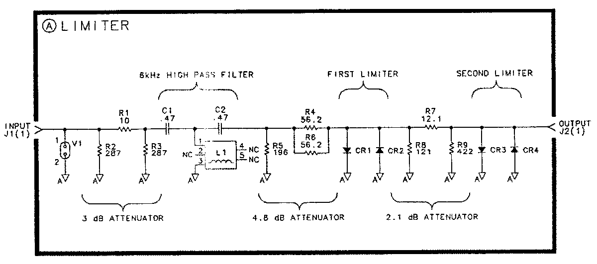
The HP 11947A is a 10 dB attenuator and transient limiter that operates from 9 kHz – 200 MHz and also incorporates a 6 kHz high-pass filter. The limiter protects RF test equipment against transient power levels that might otherwise damage the front end. It is typically used between a spectrum analyzer and the measurement port of a line impedance stabilization network (LISN). The 11947A is obsolete and hard-to-find, but the original schematic and parts list are available, so I made a clone and shrunk the design using surface mount parts. I also tuned a few of the resistor values to be closer to ideal resistive pad numbers and the result is the “11947B.”
Construction
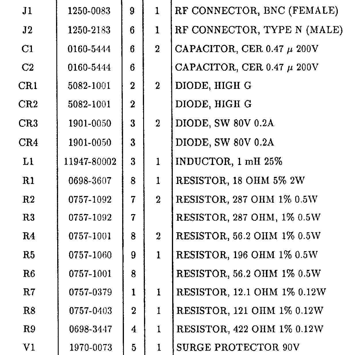
The parts list for the 11947A is in its manual and finding replacement surface-mount passive components was easy. The V1 “SURGE PROTECTOR 90V” part, based on its shape and rating, I determined had to be a gas discharge tube, so I chose a suitable 90 V surface mount GDT. The only remaining questions were the diodes. CR1 and CR2 are described simply as “DIODE, HIGH G,” but a search of its part number, 5082-1001, turned up a datasheet that indicated it was equivalent to the 1N4456. The closest available replacement I could find is the 1N4150. Its forward conduction chart is a close match to the 5082-1001 datasheet. CR3 and CR4 are smaller diodes with a 80 V, 200 mA rating, and I picked the 1N4448.
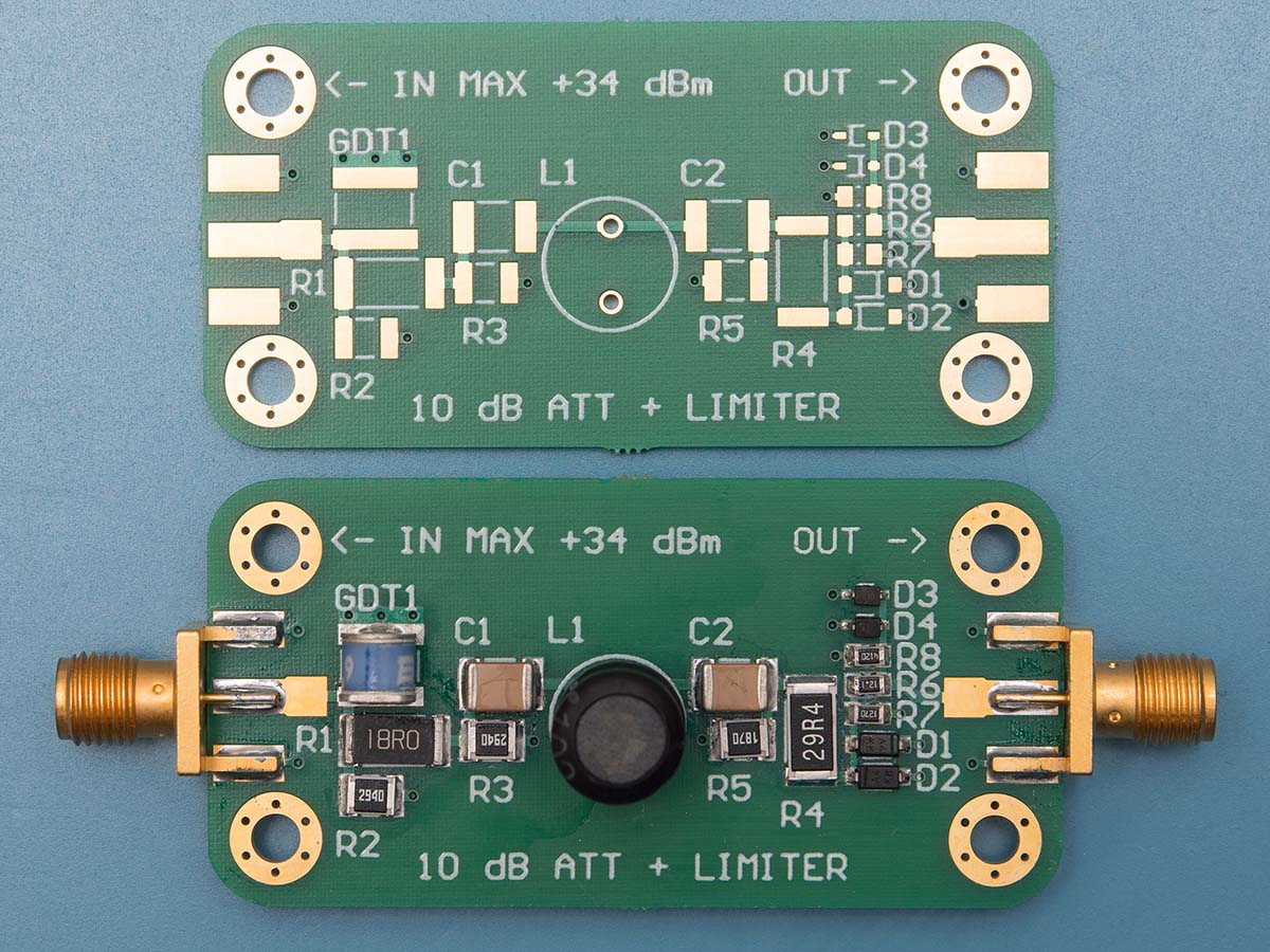
For the connectors, I used SMA end-launch connectors. This compact setup means the board can be mounted in an enclosure and connected to bulkhead connectors of any style (BNC and N are used in the 11947A) using short coaxial cables.
Evaluation
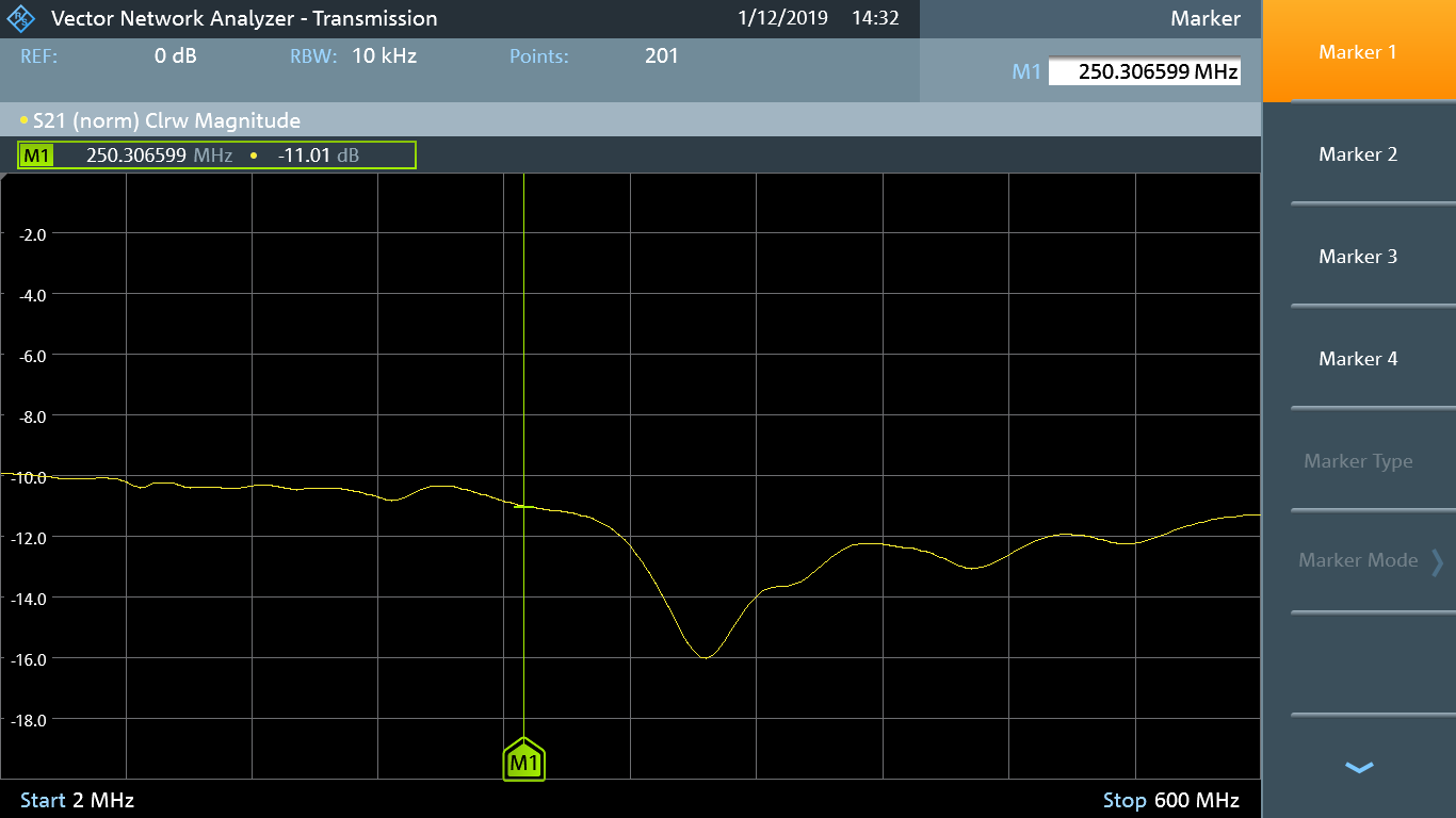
After assembling the prototype boards, I measured their performance on a R&S FPC-1500 spectrum analyzer. The attenuation stays 10 dB nominal until around 250 MHz, which satisfies the upper limit spec of 200 MHz.
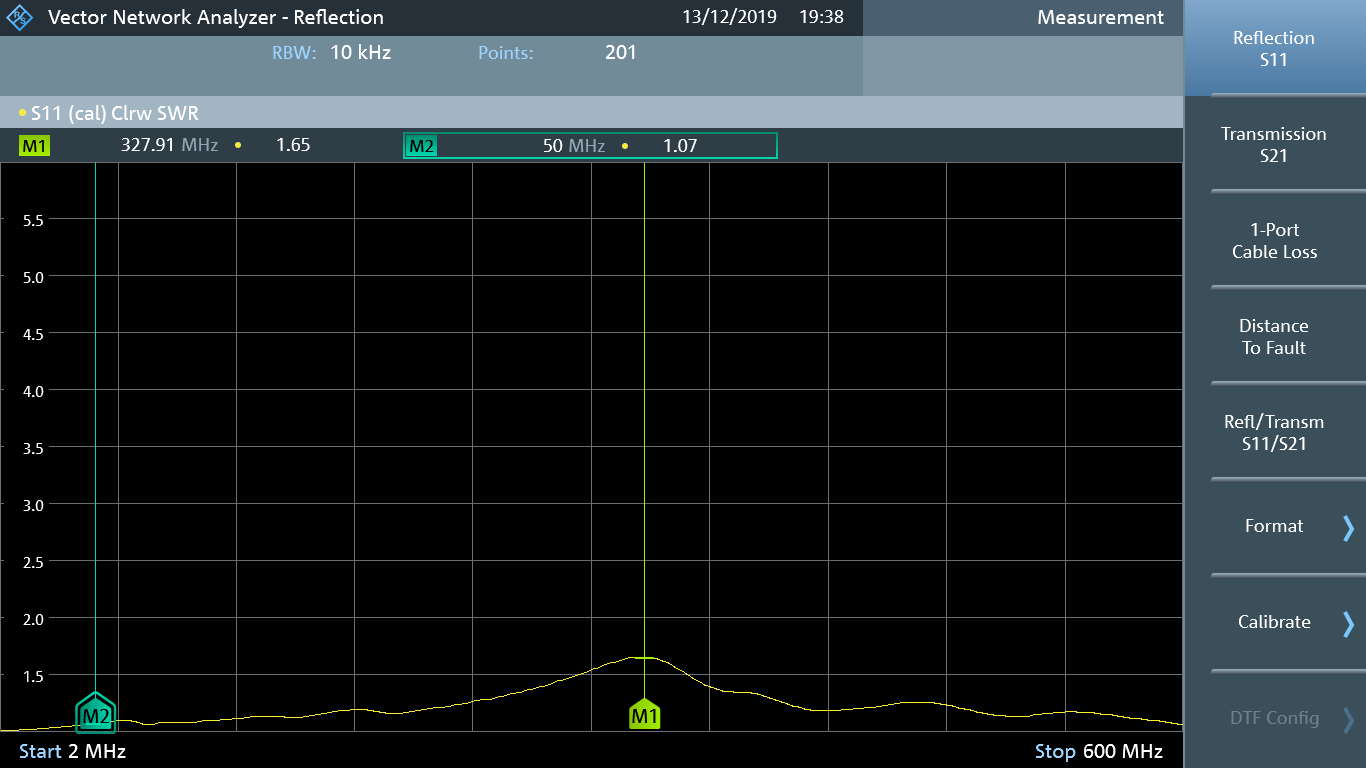
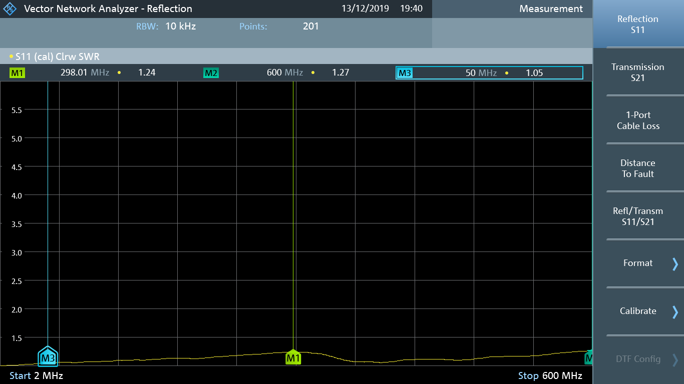
The 11947A datasheet cites a VSWR of <1.7, and <1.3 below 50 MHz for the input port. Using the FPC-1500’s 1-port VNA, I measured S11 and found the value at 200 MHz is 1.16. This is well within spec, even beyond the operating range. The output port VSWR also meets the original spec of <1.8, and <1.2 below 50 MHz.
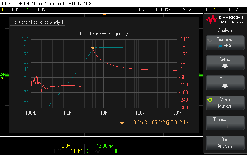
Since the FPC-1500 measurement range bottoms out at 2 MHz, I examined the low-frequency performance on an oscilloscope using the frequency response analysis feature. For this configuration, the 11947B output is connected to the oscilloscope port via a 50 Ω feed-through termination to have 50 Ω source and load impedances. The low-frequency roll-off occurs around 5–6 kHz with a flat response up to 1 MHz.
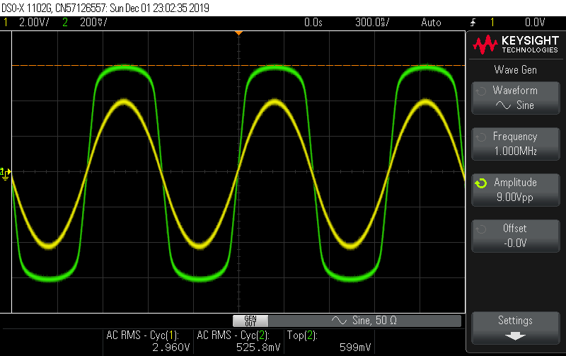
To examine the limiter performance, I stayed on the oscilloscope and increased the generator amplitude. The limiter becomes active (+10% increase in attenuation) at +14.6 dBm input power. Increasing the generator output further, the limiter distortion becomes highly visible. The top output voltage is 600 mV. An upper bound on the output power would be a square wave with amplitude of 600 mV for a RMS voltage of the same. At a system impedance of 50 Ω, the power output is limited to +8.6 dBm.
All told, the attenuator and limiter function well within spec and on the first board spin. Thanks HP engineers for the excellent design!